Circuit Diagram Of Adder Using Op Amp Solved The Op Amp In T
[diagram] bcd adder circuit diagram Solved the op amp in the adder-subtracter circuit shown in Op-amp adder
Op Amp Equations - Tessshebaylo
Summing amplifier or op amp adder circuit diagram 10+ half adder diagram What are operational amplifiers and their basic applications?
What is an audio mixer?
Inverting operational amplifiers adder subtractor equations amplifier negative calculatorSolved the op amp in the adder-subtracter circuit shown in Solved the op amp in the adder-subtracter circuit shown inSingle supply alternative to tl082 op-amp.
Inverting summing amplifier circuit diagramCircuit amplifier instrumentation tl082 input Op amp adder mixer circuit amplifier operational audio inverting summer opamp add adding voltage based combine current mixers used offFull adder circuit diagram.

Adder circuit op amp
Op amp subtractorIntroduction to ideal op-amp circuit characteristics Block diagram of basic full adder circuitAdder op amp amplifier summing circuit diagram thakur kamna jul.
Basic op amp-based adder circuit.Solved shows a op-amp adder, calculate the output voltage. Basic op amp-based adder circuit.Adder op amp circuit.

Adder multisim
Op amp adder circuit diagramAdder logic gates theory binary circuits numbers bits nand calculator equations along Full adder circuit: theory, truth table & constructionFull adder : circuit diagram, truth table, equations & verilog code.
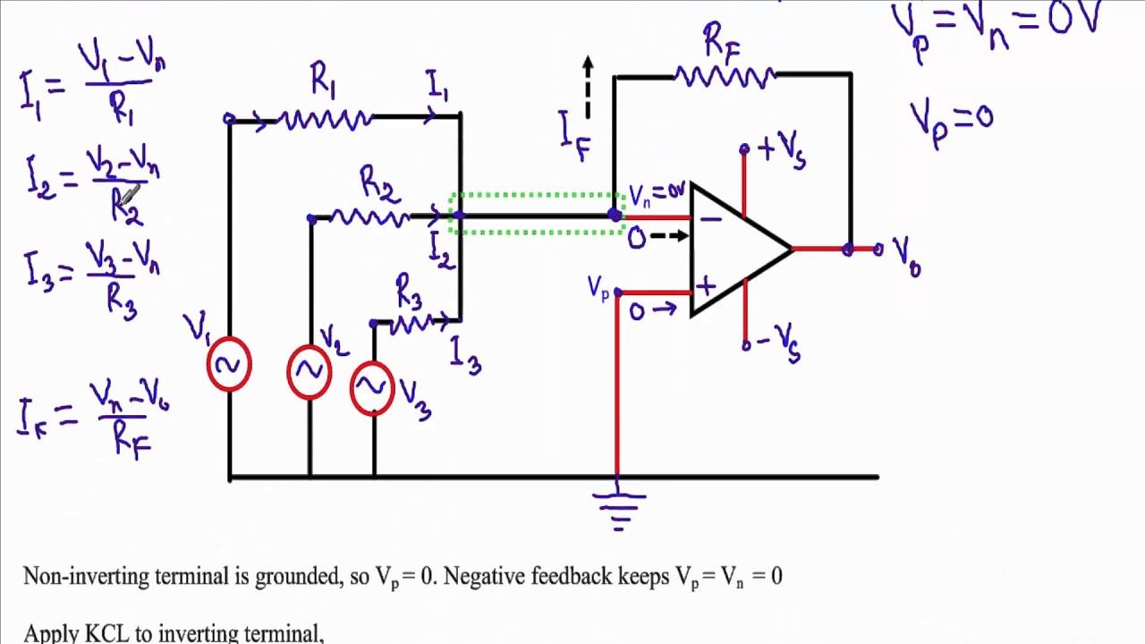
Adder circuit using 741 op ampAdder circuit application of op-amp || #msmaths #analogelectronics Adder op amp voltage output calculate shows 2v show assume transcribed textAdder circuit using #op-amp.

Adder circuit using 741 op amp
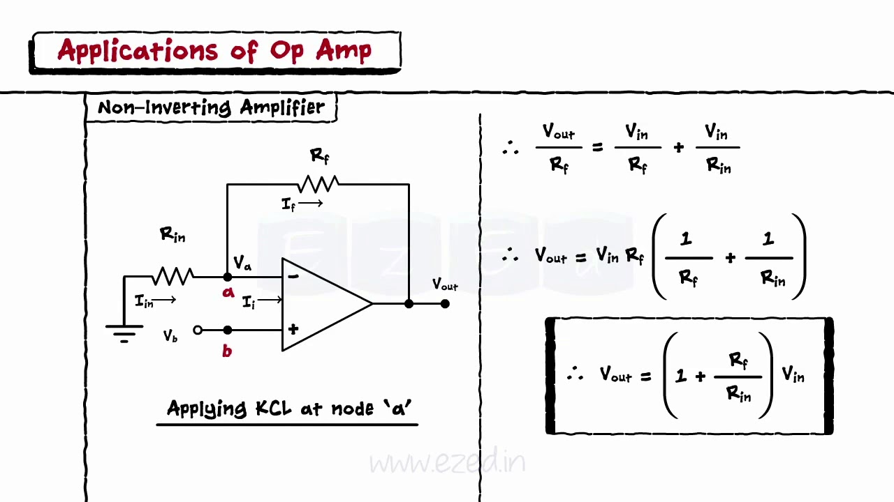
Adder circuit full diagram basic gates using truth tableNon inverting summing amplifier circuit diagram Op amp equationsSumming amplifier or op amp adder circuit.
Adder xor carry rangkaian ripple adders sum theorycircuit schematic transistor kombinasiFull adder circuit – how it works Adder circuit op ampAdder circuit using 741 op amp.

Adder subtractor inverting amps
3) summing amplifierSolved the op amp in the adder-subtracter circuit shown, is .
.


Op Amp Subtractor

Summing Amplifier or Op Amp Adder Circuit - LM358
Non Inverting Summing Amplifier Circuit Diagram

Solved Shows a Op-amp adder, calculate the output voltage. | Chegg.com

Adder CIrcuit using #Op-Amp | #Multisim #Simulation | Summer Circuit Op
Op Amp Equations - Tessshebaylo

Full Adder Circuit: Theory, Truth Table & Construction